Independent grid code testing · For global utilities, IPPs and OEMs
Home/ Behind the Grid/ BESS · Forward-looking/ BESS capability curve testing
Field methodology BESS IEEE 2800 12 min read

BESS capability curve testing: P-Q envelopes, IEEE 2800, and the four-quadrant problem.

A battery's capability envelope is a different animal from a synchronous generator's. The physics are different, the constraints bind in different regions, and the test sequence has to cover four quadrants rather than two.

BESS P-Q envelope overlay at 30/50/70/90% state-of-charge
Same battery, four envelopes · Capability shrinks at SoC extremes

A synchronous generator's P-Q envelope is shaped by thermal limits in the stator, the rotor, and the end-region core. A battery storage system's envelope is shaped by something else entirely: inverter electronics, battery state-of-charge, and DC-bus voltage.

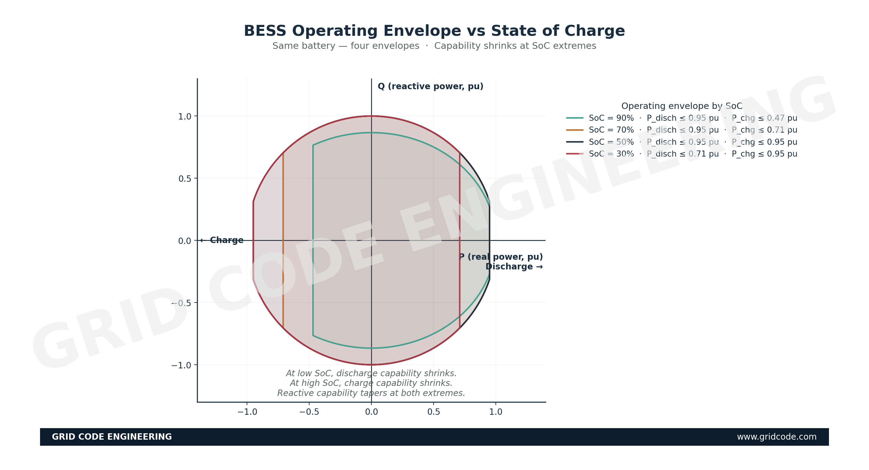
The biggest single difference is that a battery operates in four quadrants of the P-Q plane rather than two. A synchronous generator generally exports real power and exchanges reactive either direction — two quadrants. A battery actively cycles between charge and discharge. All four quadrants are operating points the regulator expects to be tested.

Three physical constraints

Inverter MVA · DC voltage · DC current — each binds in a different region.

01

Inverter MVA limit

The most-binding constraint at most operating points. Maximum apparent power per inverter, with the BESS plant aggregating multiple inverters in parallel. Same on charge and discharge — the inverter doesn't care which direction current flows.

Binds · Circle around origin
02

DC voltage / battery state

Below a minimum DC-bus voltage, the inverter cannot synthesize the AC waveform without distortion. Voltage depends on SoC, which is non-linear. Shrinks envelope at SoC extremes (very low during discharge, very high during charge).

Binds · Extreme SoC
03

DC current / cell limit

When demanded power requires DC current exceeding the battery's safe rating. Most often a concern at low SoC during high-power discharge, when battery voltage is depressed and the inverter draws more current to deliver the demanded power.

Binds · Low SoC, high P discharge

The IEEE 2800 frame

IEEE 2800-2022 — "Interconnection and Interoperability of Inverter-Based Resources Interconnecting with Associated Transmission Electric Power Systems" — is the global reference for what a regulator should ask of an inverter-based resource. It specifies the P-Q envelope shape, ride-through obligations, frequency response (PFR/FFR), and harmonic/waveform quality limits.

Most modern grid codes are moving toward IEEE 2800 alignment. Mexico's CENACE codifies reactive obligations for inverter-based resources that map closely to the IEEE 2800 envelope. Chile's NTSyCS does similar work from a slightly different starting point. Brazil's ONS submódulos, Morocco's Code du Réseau, and Saudi Arabia's SAGC are all converging on the same direction. The implementation differs; the destination is similar.

Utility-scale battery storage containers at a BESS facility under compliance testing
Battery storage facility · Where four-quadrant capability is measured
Where local codes diverge from IEEE 2800

Design the test against the stricter envelope. One campaign satisfies both.

IEEE 2800-2022 — minimum required

Rectangular minimum envelope

  • Specified at the inverter AC terminals
  • Q range across the full real-power range
  • Ride-through and PFR/FFR obligations defined
  • Reference framework for inverter-based resources globally
Local grid codes (Mexico, Chile, others)

Larger envelope at the POC

  • Reactive obligations referenced to the POC, not inverter terminals
  • Step-up transformer impedance corrections required
  • Local telemetry requirements beyond IEEE 2800
  • PFR/FFR droop and deadband values may differ from the IEEE reference

How the test campaign is structured

Phase 1 — static envelope verification at multiple SoC points. The BESS is brought to a defined SoC (typically 30%, 50%, 70%, 90%) and held there. At each SoC, the inverter is commanded to step through a series of P-Q operating points covering the four quadrants. Result: a mapped envelope at each SoC.

Phase 2 — dynamic step response. At a defined SoC (typically 50%), the BESS is commanded to step from one operating point to another and the transient response is captured at high sample rate (1–10 ms). Validates that control loops are tuned correctly and regulator-specified response times are achievable.

Phase 3 — voltage and frequency ride-through. The BESS is exposed to controlled voltage sags and frequency excursions. Captures whether it rides through, whether it disconnects, what the post-event behavior is, and whether it supports the grid actively during the event (for grid-forming inverters).

What the field engineer cares about.

  1. The DC side is half the story

    A BESS test that measures only the AC-side response is missing the constraints that actually shape the envelope. DC-bus voltage, BMS reports, cell condition data are part of the test record.

  2. SoC sweep takes calendar time

    Bringing the BESS to defined SoC points, holding, testing — paced by safe charge/discharge rate. A four-SoC sweep on a substantial BESS is a week of field time, not a day.

  3. Coordinate with the system operator

    BESS at full reactive export moves the local bus voltage. Operator notification matters more than for synchronous generators — BESS movements are faster and can be larger per inverter.

  4. Verify inverter firmware against documented control philosophy

    BESS firmware updates more frequently than synchronous excitation systems. Today's test validates today's firmware.

  5. Capture data in a dossier-portable format

    Regulators may request specific waveform formats. Flexible recorder configuration with redundant time bases and metadata allows reformatting later without re-doing the test.

The four-quadrant problem is what makes BESS capability characterization distinct from synchronous-generator characterization. The four-quadrant solution is to test all four quadrants, at multiple SoC points, with all the diagnostic data captured — and to keep IEEE 2800 in one hand and the local grid code in the other while designing the test sequence.

Verify against published regulation

The current IEEE 2800 version reference (the 2022 version is cited here), whether the applicable grid code has specific articles dedicated to inverter-based resources or treats them within the broader generator framework, and the precise PFR/FFR droop and deadband values codified for BESS in each jurisdiction should be confirmed against the active grid code. The structural framework described here (three constraints, four quadrants, three-phase test campaign) is general and universal.

BESS approaching commercial operation? Let’s discuss your capability campaign.